How to Choose Fiber Optic Cable Connectors
Choosing the right fiber optic cable connectors can determine whether a network performs reliably or struggles with constant signal loss. Connector type, polishing method, insertion loss, return loss, and environmental protection all influence the final result. A connector that works well in a clean server room may fail in a dusty industrial cabinet.
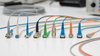
This guide explains how experienced installers evaluate connectors before making a purchase. It considers common options such as LC, SC, ST, and MPO connectors. Each design serves different space, density, and maintenance requirements. For example, an LC connector fits neatly into high-density panels, while an SC connector offers a larger body that many technicians handle easily. Small details matter. A loose dust cap can expose the ferrule to contamination.
Reliable selection also requires attention to fiber type and polishing style. Single-mode systems often demand tighter performance control than short multimode links. UPC and APC finishes should not be mixed casually, especially in systems sensitive to reflection. Manufacturer specifications provide useful guidance, but field conditions can reveal problems that a datasheet does not show.
There is no perfect connector.
A practical decision should balance performance, compatibility, installation skill, cleaning procedures, and long-term serviceability. Testing with an inspection scope and optical loss test equipment remains essential. Even experienced technicians sometimes overlook connector cleanliness. That mistake is easy to make and expensive to ignore. By examining these real-world factors, this article provides a clearer, more dependable path toward selecting fiber optic cable connectors for modern communication networks.

Define the Role of Fiber Optic Cable Connectors
Fiber optic cable connectors are the small interfaces that make a larger network usable. Their main role is precise alignment. They hold two fiber cores face to face, allowing light to cross with minimal loss. A connector also creates a repeatable connection for installation, testing, maintenance, and future changes. Without it, technicians would need to splice every cable permanently. That would reduce flexibility and increase repair time.
In practical work, connector choice should follow the cable’s job, not appearance. A data-center link may need frequent disconnection, while a buried route may prioritize protection and sealing. Key factors include insertion loss, return loss, connector type, fiber mode, end-face quality, and environmental rating. Cleanliness matters greatly. One tiny dust particle can disrupt the optical path. I once focused too much on connector housing strength and overlooked inspection discipline. That assumption was too simple.
Reliable connectors also support accurate testing. They provide a stable reference point for power meters, light sources, and fault-location tools. However, a connector cannot correct poor polishing, weak strain relief, or careless installation. Choose components with documented performance and compatible tolerances. Check the mating cycle requirement. Confirm whether the connection will face vibration, moisture, heat, or repeated handling. A connector is not merely an accessory. It is the controlled junction between fragile glass and the working network.
Match Connector Types to Fiber and Network Requirements
Choosing a fiber optic connector starts with the fiber, not the connector shape. In field installations, this simple order prevents costly rework. Single-mode fiber usually needs tighter alignment and low-loss performance over long distances. Multimode links often serve shorter runs inside buildings. Their connector choice still depends on core size, polarity, and equipment ports. Check the cable specification before ordering anything. Measure twice.
LC connectors suit high-density panels because their small bodies conserve rack space. SC connectors offer a larger push-pull design, which can help during frequent service work. ST connectors use a twist-lock mechanism and may fit older infrastructure. MPO-style connectors support many fibers in one interface, but polarity planning becomes critical. A wrong polarity can leave a healthy link unusable. It is an easy mistake.
Network requirements should guide the final decision. For high-speed links, verify insertion loss, return loss, cleaning standards, and transceiver compatibility. In harsh areas, select secure housings and strain relief suited to dust, vibration, or moisture. I have seen technicians choose by price, then discover insufficient panel space. That lesson is uncomfortable but useful. Test every terminated link with inspection and measurement equipment. Record polarity, fiber type, and test results for future maintenance. Leave room for uncertainty; cable routes and adapters rarely behave exactly as drawings suggest.
Compare Polishing Styles, Performance, and Installation Methods
Choosing a fiber optic cable connector depends on polishing style, performance needs, and installation conditions. A polished connector usually offers better alignment than a basic flat finish. PC polishing reduces air gaps at the fiber end. UPC polishing improves return loss through a finer, curved surface. APC polishing uses an angled end face, often around eight degrees, to reduce reflected light in sensitive networks.
Performance should be checked with measured data, not assumptions. In field testing, insertion loss below 0.3 dB is a useful target for many links. Return loss matters greatly in high-speed and long-distance systems. APC connectors can perform well in these applications, but they require matching APC adapters. Mixing polishing types can create poor contact and unstable readings. I have seen clean-looking connectors fail after repeated reconnection. End-face inspection is not optional. Dust is small, but its effect is not.
Tips: Clean, inspect, and test every connector before final installation. Factory-terminated cables save time and reduce field errors. Field termination offers flexibility, but it needs trained hands and careful curing. Leave enough service loop near the enclosure. Tight bends can increase loss later. Do not trust color alone; verify the connector type and polish angle. My own installation plans have sometimes underestimated access space, so a simple measurement before pulling cable is worth the extra minute.
How to Choose Fiber Optic Cable Connectors
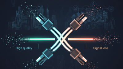
Polishing style directly affects reflected light and signal quality. PC connectors typically provide about 35 dB return loss, UPC connectors about 50 dB, and APC connectors about 60 dB. A lower insertion-loss value indicates less optical power is lost at the connection.
Factory-terminated connectors offer consistent performance and fast installation. Field-terminated epoxy-and-polish connectors require specialist tools and inspection, while mechanical field-installable connectors reduce installation time but may have more variation. Use PC or UPC for general links and APC where low back reflection is important, such as analog video, passive optical networks, and sensitive test systems.
Evaluate Quality, Maintenance Needs, and Total Cost
How to Choose Fiber Optic Cable Connectors
Connector quality should be measured, not guessed. Check insertion loss, return loss, endface geometry, and pull strength against applicable IEC and TIA requirements. A clean endface matters. IEC 61300-3-35 defines inspection methods for scratches, pits, and contamination. Field technicians should inspect both sides before mating. Dust can create unstable readings and permanent damage.
Maintenance needs influence the real purchase price. Select connectors with clear polarity, secure latching, and accessible inspection points. High-density panels may save rack space, yet they can slow cleaning and testing. That trade-off is easy to miss. A practical maintenance log should record inspection dates, test results, and replacement events. The Fiber Optic Association’s installation guidance repeatedly emphasizes inspection, cleaning, and verification before connection.
Total cost includes downtime, labor, test equipment, and future replacements. Uptime Institute’s 2023 Annual Outage Analysis reported that 25% of respondents experiencing serious outages reported costs above one million dollars. That figure is not connector-specific, but it shows why small optical faults deserve attention. The Ponemon Institute’s Cost of Data Center Outage study estimated an average outage cost of about $740,000. The study is dated, so it should not be treated as a current price list. Still, it offers useful perspective. Spending slightly more on reliable connectors may reduce repeated troubleshooting, but only when installation quality remains consistent.