
How to Choose the Right Wire Cable for Your Project?
Choosing the right wire cable begins with the conditions around the installation, not the product label alone. A cable running through a warm control cabinet faces different demands than one buried outdoors. Current load, voltage drop, distance, bend radius, and insulation temperature all influence performance. Small details matter. A rushed choice can create heat, signal loss, or premature failure.
In field projects, I have seen a cable look suitable until the route changed. The bend became tighter. The motor started drawing more current. That experience is easy to overlook when reviewing a neat specification sheet. Check conductor material, cross-sectional area, shielding, jacket resistance, and connector compatibility. For data applications, impedance and noise control may matter more than raw size. For power systems, verified ampacity and voltage-drop calculations deserve careful attention. Manufacturer datasheets and recognized installation standards provide a stronger basis than guesswork.
There is no universal wire cable. The cheapest option may become expensive after replacement, downtime, or rewiring. Still, over-specifying every project wastes money and can complicate installation. The sensible choice balances safety, durability, performance, and service conditions. This guide explains how to compare those factors clearly, while acknowledging an uncomfortable truth: project information is often incomplete. When uncertain, measure the route, confirm the load, consult a qualified professional, and document the decision before installation.
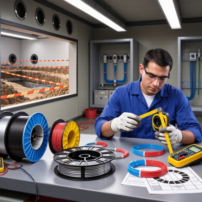
Define the Project’s Electrical and Mechanical Requirements
How to Choose the Right Wire Cable for Your Project?
Define the electrical load before comparing cable prices. Record voltage, continuous current, starting current, frequency, and allowable voltage drop. A motor can draw several times its running current during startup. Ignoring that detail may cause nuisance trips or overheated conductors.
The IEA’s Electricity 2024 report forecasts global electricity demand to grow by about 4% annually through 2026. More equipment means tighter margins for poorly planned circuits. Use conductor resistance data from IEC 60228, then check ampacity against the installation method. Cables in a hot conduit carry less current than cables in open air. Keep the calculation specific.
Mechanical conditions matter just as much. Measure bending radius, pulling tension, vibration, moisture, chemicals, and impact exposure. A flexible cable may suit a moving machine, while a rigid installation needs stronger mechanical protection. NFPA’s Electrical Fires report recorded an estimated 32,620 U.S. home fires involving electrical distribution and lighting equipment annually from 2015 to 2019. The report also linked these fires to about 470 civilian deaths each year. That number deserves attention.
A neat spreadsheet can still miss a damaged entry point. Inspect the route. Recheck the terminals. Leave practical space for maintenance, because real installations rarely remain perfect.
How to Choose the Right Wire Cable for Your Project? – Define the Project’s Electrical and Mechanical Requirements
| Requirement Dimension | Key Design Question | Typical Data or Selection Range | Recommended Cable Characteristics | Important Verification Point |
|---|---|---|---|---|
| Conductor Material | What level of conductivity, flexibility, and installation durability is required? | Copper: high conductivity and good flexibility Aluminum: lower weight and lower material cost |
Use copper where compact size, repeated flexing, or higher conductivity is important. Consider aluminum for suitable fixed installations where weight and cost are major factors. | Confirm compatibility with terminals, connectors, installation standards, and corrosion-control requirements. |
| Conductor Size | How much current must the conductor carry without excessive heating or voltage drop? | Common cross-sectional areas: 0.5 mm², 0.75 mm², 1.5 mm², 2.5 mm², 4 mm², 6 mm², 10 mm² and larger | Select the conductor area according to allowable ampacity, ambient temperature, installation method, grouping, insulation temperature rating, and permissible voltage drop. | Do not select size from current alone; apply the relevant electrical code and correction factors. |
| Rated Voltage | What is the highest system voltage, including possible transient conditions? | Typical low-voltage cable ratings include 300/500 V, 450/750 V, and 0.6/1 kV | Choose a cable with a rated voltage equal to or greater than the system requirement and suitable insulation coordination. | Check line-to-line and line-to-ground voltage, transient exposure, and the applicable product standard. |
| Current Load | What continuous and intermittent current will flow through the cable? | Determine normal load current, starting current, short-duration overloads, and duty cycle | Use an ampacity calculation that accounts for conductor size, installation conditions, conductor grouping, and thermal environment. | Motors, transformers, and other inductive loads may require separate starting-current and protection calculations. |
| Voltage Drop | How much voltage loss can the connected equipment tolerate? | A commonly used design target is approximately 3% for branch circuits, with total circuit drop often limited to about 5%, subject to local requirements | Increase conductor size, reduce cable length, or select a lower-resistance conductor when voltage drop exceeds the project limit. | Calculate using circuit length, load current, conductor resistance, power factor, and circuit configuration. |
| Insulation Material | What temperature, moisture, chemical, and flexibility conditions will the insulation experience? | Common materials include PVC, XLPE, polyethylene, elastomeric compounds, and fluoropolymer materials | Choose insulation according to conductor temperature rating, oil or chemical exposure, moisture resistance, flame performance, and required flexibility. | Verify both normal operating temperature and the permitted short-circuit temperature. |
| Operating Temperature | What are the minimum, maximum, and continuous operating temperatures? | Common cable ratings include 70°C, 90°C, 105°C, and higher for specialized constructions | Select insulation and jacket materials rated above the expected continuous temperature, while considering derating at elevated ambient temperatures. | The allowable cable temperature may also be limited by terminals, connectors, conduits, or surrounding materials. |
| Installation Environment | Will the cable be installed indoors, outdoors, underground, in a conduit, or in a wet location? | Possible exposures: water, humidity, sunlight, soil, dust, salt spray, oils, and corrosive chemicals | Use a moisture-resistant, sunlight-resistant, direct-burial, oil-resistant, or corrosion-resistant construction when required by the environment. | Confirm the cable marking and installation method are approved for the specific location. |
| Mechanical Flexibility | Will the cable remain stationary or move repeatedly during operation? | Fixed installation, occasional movement, continuous flexing, torsion, or drag-chain service | Use solid conductors mainly for fixed wiring. Use stranded or finely stranded conductors for movement, vibration, and repeated bending. | Check the manufacturer-specified minimum bend radius and flexing cycle requirements. |
| Bend Radius | How much installation space is available for routing and termination? | Minimum bend radius is construction-specific and is commonly expressed as a multiple of the cable outside diameter | Choose a cable whose required bend radius fits the available pathway without forcing sharp bends or damaging insulation. | The required radius may be different during installation and during service, especially for flexible cables. |
| Tensile and Crush Loads | Will the cable be pulled, suspended, compressed, or exposed to impact? | Assess pulling tension, cable weight, crush pressure, impact energy, and support spacing | Use reinforced or armored constructions where mechanical protection is required. Provide suitable pulling equipment and cable supports. | Do not exceed the permitted pulling tension or apply pulling force to conductors that are not designed for it. |
| Shielding and Electromagnetic Compatibility | Could electrical noise interfere with signals or sensitive equipment? | Potential sources include variable-speed drives, motors, relays, switching power supplies, and radio-frequency equipment | Use twisted pairs, foil shields, braided shields, overall shields, or combinations appropriate to the noise frequency and grounding arrangement. | Plan shield termination, grounding, separation from power cables, and routing before installation. |
| Number of Cores | How many power, signal, control, protective-earth, or neutral conductors are needed? | Single-core, two-core, three-core, four-core, multi-core, or paired constructions | Select enough cores for the circuit, control functions, grounding arrangement, and future expansion where justified. | Avoid unused cores that increase diameter and cost unless they provide a defined maintenance or expansion benefit. |
| Fire Performance | What fire, smoke, and flame behavior is required in the installation? | Requirements may include flame retardance, low smoke emission, low halogen content, or circuit integrity | Choose the fire-performance classification required for the building, transport system, industrial area, or emergency circuit. | Fire performance requirements vary by location and code; verify the complete cable assembly, not only the conductor insulation. |
| Termination Compatibility | Will the cable fit the selected terminals, glands, lugs, connectors, and protection devices? | Check conductor size, strand class, insulation diameter, terminal temperature rating, and entry dimensions | Select a cable construction that can be correctly stripped, crimped, clamped, sealed, and supported by the termination hardware. | Verify torque values, preparation length, bend support, and compatibility between dissimilar metals. |
| Compliance and Documentation | Which electrical codes, product standards, and project documents apply? | May include national wiring rules, installation codes, environmental classifications, and cable construction standards | Specify required markings, test reports, conductor identification, batch traceability, and installation documentation. | Final selection should be reviewed by a qualified electrical professional and approved for the project jurisdiction. |
Related Posts
-
How to Choose the Right Wire Cable for Your Electrical Project
-

2025 How to Choose the Right Wire Cable for Your Projects Effectively
-
China Best Cord Management Solutions for a Tidy Workspace?
-

What is Telephone Cable and How Does it Work in Modern Communication
-
How to Choose the Right BNC Adapter for Your Needs: A Complete Guide
-

How to Choose Fiber Optic Cable Connectors